Harvestree provides four measurement ports with industrial M8 connectors. Each port is assigned a measurement mode in software and paired with a compatible probe. All active ports are acquired in one pass and sent in a single LoRaWAN uplink.
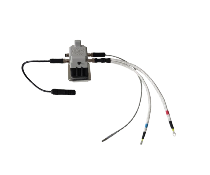
Modes are set in Toolbox only (not downlink). Changing a port’s mode clears that port’s calibration and alarms. Use catalog probes, or third-party / custom only with MOIZ approval. Payload combinations that exceed 51 B are blocked at commission time.
Modes by family
Environmental
Voltage
Magnetic field
Current
Industrial analog
Vibration & contacts
Mode descriptions
Check catalog for compatible physical probes.
PT1000 (RTD)
Temperature (°C) from a Pt1000 element with on-board excitation.
Hardware: MOIZ-qualified Pt1000 / RTD M8 assemblies from the catalog, or third-party RTD within the qualified range (written MOIZ approval).
In the field: Mate the probe fully. Select PT1000 in Toolbox, confirm readings. Optional calibration in Toolbox if you need a site correction.
Thermocouple (K, J, T, N, S, E, B, R)
Cold-junction temperature (°C) and hot-junction temperature (°C) for the thermocouple type selected in Toolbox.
Hardware: MOIZ-qualified thermocouple adapter (catalog).
In the field: Fit the TC adapter and place the hot junction on the process. Select Thermocouple in Toolbox (type K–R), confirm readings. Optional calibration in Toolbox if you need a site correction.
Digital temperature probe
Temperature (°C) from a digital probe on the sensor bus.
Hardware: MOIZ-qualified digital temperature probe (catalog).
In the field: Mate the digital probe. Select Digital temperature probe in Toolbox, confirm readings. Optional calibration in Toolbox if you need a site correction.
Infrared
Object temperature (°C) from a non-contact infrared probe.
Hardware: MOIZ-qualified infrared temperature probe / interface (catalog).
In the field: Aim at the target (FoV, distance, reflections). Select Infrared in Toolbox; set emissivity for the surface when needed.
Temperature & humidity
Ambient temperature (°C) and relative humidity (%RH). JSON also exposes a frost index (icing-risk indicator): the reference decoder computes it from T/RH; the 5th uplink byte is reserved for layout compatibility and is not the JSON source.
Hardware: MOIZ-qualified temperature & humidity module (catalog).
In the field: Mount in free air. Select Temperature & humidity in Toolbox; use frost as icing-risk context only. Optional calibration in Toolbox if you need a site correction (device frost alarms use the on-device corrected value; cloud JSON frost follows the decoder formula).
Sound level
A-weighted sound level (dB) from a digital probe on the sensor bus.
Hardware: MOIZ-qualified sound-level probe (catalog).
In the field: Mount in free air (unobstructed path to the microphone; avoid direct airflow). Select Sound level in Toolbox, confirm readings. Optional calibration in Toolbox if you need a site correction.
Gauge pressure
Gauge pressure (psi) and sensor temperature (°C) from a digital pressure transducer on the sensor bus.
Hardware: MOIZ-qualified pressure transducer (catalog).
In the field: Fit the pressure port (media-compatible) and mate the I2C cable. Select Gauge pressure in Toolbox, confirm readings. Optional calibration in Toolbox if you need a site correction.
DC voltage
DC voltage (mV) on a single-ended input.
Hardware: MOIZ-qualified DC voltage assemblies / cabling from the catalog, or third-party wiring within the qualified range (written MOIZ approval).
In the field: Wire single-ended within the qualified range. Select DC voltage in Toolbox, confirm readings. Optional calibration in Toolbox if you need a site correction.
AC voltage (RMS)
AC voltage RMS (mV) and frequency (Hz) on a single-ended input. AC analysis: dominant band 20–100 Hz — not wideband true-RMS.
Hardware: MOIZ-qualified AC voltage assemblies / cabling from the catalog, or third-party wiring within the qualified range (written MOIZ approval).
In the field: Wire single-ended within the qualified range. Select AC voltage in Toolbox, confirm readings. Optional calibration in Toolbox if you need a site correction.
DC differential voltage
DC differential voltage (mV) on a differential pair (floating / small signals) via the built-in differential input.
Hardware: MOIZ-qualified DC differential assemblies / cabling from the catalog, or third-party wiring within the qualified CM / differential range (written MOIZ approval).
In the field: Wire the differential pair (polarity, CM limits). Select DC differential voltage in Toolbox, confirm readings. Optional calibration in Toolbox if you need a site correction.
AC differential voltage (RMS)
AC differential voltage RMS (mV) and frequency (Hz) on a differential pair via the built-in differential input. AC analysis: dominant band 20–100 Hz — not wideband true-RMS.
Hardware: MOIZ-qualified AC differential assemblies / cabling from the catalog, or third-party wiring within the qualified range (written MOIZ approval).
In the field: Wire the differential pair (polarity, CM limits). Select AC differential voltage in Toolbox, confirm readings. Optional calibration in Toolbox if you need a site correction.
DC differential + external amplifier
DC differential voltage (mV, default) through an external amplifier (packaged gains).
Hardware: MOIZ-qualified external amplifier (catalog).
In the field: Wire the external amplifier to the product. Select DC differential + external amplifier in Toolbox; set the matching gain preset, confirm readings.
AC differential + external amplifier (RMS)
AC differential voltage RMS (mV, default) and frequency (Hz) through an external amplifier (packaged gains). AC analysis: dominant band 20–100 Hz — not wideband true-RMS.
Hardware: MOIZ-qualified external amplifier (catalog).
In the field: Wire the external amplifier to the product. Select AC differential + external amplifier in Toolbox; set the matching gain preset, confirm readings.
DC magnetic sensor
DC magnetic field (engineering units from the sensor-type preset).
Hardware: MOIZ-qualified magnetic probe (catalog).
In the field: Mount with a controlled air gap; mind stray fields. Select DC magnetic sensor in Toolbox; set the matching sensor-type preset, confirm readings.
AC magnetic sensor (RMS)
AC magnetic-field RMS (engineering units from the sensor-type preset) and frequency (Hz). AC analysis: dominant band 20–100 Hz — not wideband true-RMS.
Hardware: MOIZ-qualified magnetic probe (catalog).
In the field: Mount with a controlled air gap; mind stray fields. Select AC magnetic sensor in Toolbox; set the matching sensor-type preset, confirm readings.
DC current · voltage difference
DC current (A) from a shunt / ΔU on the built-in differential input.
Hardware: MOIZ-qualified shunt / ΔU sensing assembly (catalog).
In the field: Place the shunt / ΔU sense in the current path; watch burden and wiring. Select DC current · voltage difference in Toolbox; set zero / linear resistivity / distance, or a conversion table, confirm readings.
AC current · voltage difference (RMS)
AC current RMS (A) and frequency (Hz) from a shunt / ΔU on the built-in differential input. AC analysis: dominant band 20–100 Hz — not wideband true-RMS.
Hardware: MOIZ-qualified shunt / ΔU sensing assembly (catalog).
In the field: Place the shunt / ΔU sense in the current path; watch burden and wiring. Select AC current · voltage difference in Toolbox; set zero / linear resistivity / distance, or a conversion table, confirm readings.
AC current · CT coil (RMS)
AC current RMS (A) and frequency (Hz) from a 333 mV RMS CT that encircles the primary conductor. Not for 1 A / 5 A current-output CTs. AC analysis: dominant band 20–100 Hz — not wideband true-RMS.
Hardware: MOIZ-qualified 333 mV RMS CT assembly (catalog). Never leave a CT secondary open under load.
In the field: Clamp / thread the CT so it encircles the primary; wire the 333 mV secondary to the port; check polarity / primary rating. Select AC current · CT coil in Toolbox; set the CT scale (A/mV), confirm readings.
DC current · magnetic sensor
DC current (A) from a local magnetic field near the conductor (Hall, TMR, …). The probe sits close to the cable — it does not have to encircle it.
Hardware: MOIZ-qualified magnetic current probe (catalog).
In the field: Place the sensor near the conductor with a repeatable position and gap (orientation free as long as it stays fixed); mind nearby ferrous parts. Select DC current · magnetic sensor in Toolbox; set zero / coupling factor (A/mV), or a conversion table, confirm readings.
AC current · magnetic sensor (RMS)
AC current RMS (A) and frequency (Hz) from a local magnetic field near the conductor (Hall, TMR, …). The probe sits close to the cable — it does not have to encircle it. AC analysis: dominant band 20–100 Hz — not wideband true-RMS.
Hardware: MOIZ-qualified magnetic current probe (catalog).
In the field: Place the sensor near the conductor with a repeatable position and gap (orientation free as long as it stays fixed); mind nearby ferrous parts. Select AC current · magnetic sensor in Toolbox; set zero / coupling factor (A/mV), or a conversion table, confirm readings.
4–20 mA loop
Loop current (mA) via an on-board 120 Ω shunt (I = V / 120 Ω). The port does not power the loop (~2.4 V drop on the shunt at 20 mA). Calibration can map to engineering units.
Hardware: Externally powered 4–20 mA transmitter + MOIZ-qualified 4–20 cabling (catalog). Add external burden if the transmitter needs more than 120 Ω compliance.
In the field: Power the transmitter separately; series the loop through the MOIZ cable. Select 4–20 mA in Toolbox; set value at 4 mA and value at 20 mA, or a conversion table, confirm readings.
Potentiometer
Position / ratio (engineering units after Calibration) from a potentiometer (ratiometric analog input).
Hardware: MOIZ-qualified potentiometer / ratiometric assembly (catalog).
In the field: Wire per MOIZ pinout. Select Potentiometer in Toolbox; set value at 0% and value at 100%, or a conversion table, confirm readings.
1-axis vibration
LF velocity RMS (mm/s, default 10 Hz–1 kHz) and HF acceleration RMS (m/s², default 2–10 kHz), plus spectral energy ratios (0–1, telemetry only). Alarms use LF/HF RMS.
Hardware: MOIZ-qualified 1-axis vibration probe (catalog).
In the field: Mount rigidly on the axis of interest. Select 1-axis vibration in Toolbox; set accelerometer sensitivity and band edges, confirm readings.
Dry contact (synchronous)
Contact state (0 = open, 1 = closed) sampled on each measurement / check cycle from a voltage-free contact.
Hardware: Dry (voltage-free) contact wired to the port input (excitation defined on the product side). Do not wire wet / energized contacts.
In the field: Wire the contact. Select Dry contact (synchronous) in Toolbox; set invert logical state when needed, confirm readings. Not for microsecond pulses (bounce, cable capacitance).
Async dry contact
Contact state (0 = open, 1 = closed). In Alarm mode, a configured edge wakes the product and starts an alarm episode from that edge (short pulses are not gated on later port measurements). While the episode is active, the contact level is re-checked on each Alarm TX to hold or clear. Not a normal Ports-picker entry for Monitoring.
Hardware: Dry (voltage-free) contact wired to the port input (passive pull-up / RC; excitation defined on the product side). Do not wire wet / energized contacts. Enable Async alarm trigger (rising or falling) with application mode = Alarm.
In the field: Wire the contact. Select Async alarm trigger (rising or falling) in Toolbox with application mode = Alarm. Validate wake → alarm uplink; clearance follows the level on later Alarm TX cycles — see Operation — async state machine. No unified port calibration on this path.
JSON field names → Payload & JSON.